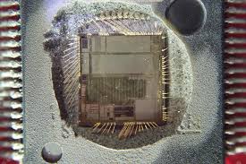
Clone Microcontroller PIC16C56A Flash Heximal
The PSA and PS2:PS0 bits (OPTION<3:0>) determine prescaler assignment and prescale ratio.
When assigned to the Timer0 module, all instructions writing to the TMR0 register (e.g., CLRF 1, MOVWF 1, BSF 1,x, etc.) will clear the prescaler by Clone Microcontroller PIC16C56A Flash Heximal. When assigned to WDT, a CLRWDT instruction will clear the prescaler along with the WDT. The prescaler is neither readable nor writable. On a RESET, the prescaler contains all ‘0’s by Crack Philip P89C51RD2H MCU Locked Eeprom.
The prescaler assignment is fully under software control (i.e., it can be changed “on the fly” during program execution). To avoid an unintended device RESET, the following instruction sequence must be executed when changing the prescaler assignment from Timer0 to the WDT when Break IC Flash.
To change prescaler from the WDT to the Timer0 module, use the sequence shown in Example 6-2. This sequence must be used even if the WDT is disabled after copy MCU PIC16F72. A CLRWDT instruction should be executed before switching the prescaler.
What sets a microcontroller apart from other processors are special circuits to deal with the needs of real-time applications. The PIC16C56A family of microcontrollers has a host of such features intended to maximize system reliability, minimize cost through elimination of external components, provide power saving operating modes and offer code protection against Copy Microcontroller MCU Microchip PIC16C63A. These features are:
• Oscillator selection
• Reset
– Power-On Reset (POR)
– Device Reset Timer (DRT)
– Wake-up from SLEEP on pin change
• Watchdog Timer (WDT)
• SLEEP
• Code protection
• ID locations
• In-circuit Serial Programming
• Clock Out
The PIC16C56A has a Watchdog Timer which can be shut off only through configuration bit WDTE. It runs off of its own RC oscillator for added reliability to Clone Microcontroller PIC16C56A Flash Heximal. If using HS, XT or LP selectable oscillator options, there is always an 18 ms (nominal) delay provided by the Device Reset Timer (DRT), intended to keep the chip in reset until the crystal oscillator is stable to support the process of Extract Microcontroller PIC12F617 Binary. If using INTRC or EXTRC there is an 18 ms delay only on VDD power-up. With this timer on-chip, most applications need no external reset circuitry.


