Clone IC ATMEGA164 Program
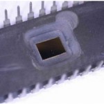
Clone IC ATMEGA164 Program from the flash memory and data from eeprom memory, the process of MCU reading needs to decapsulate the silicon package of microcontroller so microprobe tip will be able to get access to the databus from CPU processor to memory;
Clone IC ATMEGA164 Program from the flash memory and data from eeprom memory, the process of MCU reading needs to decapsulate the silicon package of microcontroller
The ATMEGA164 With all the features the External Memory Interface provides, it is well suited to operate as an interface to memory devices such as External SRAM and Flash, and peripherals such as LCD-display, A/D, and D/A. The main features are:
- Four different wait-state settings (including no wait-state).
- Independent wait-state setting for different extErnal Memory sectors (configurable sector size).
- The number of bits dedicated to address high byte is selectable.
- Bus keepers on data lines to minimize current consumption (optional).
When the eXternal MEMory (XMEM) is enabled, address space outside the internal SRAM becomes available using the dedicated External Memory pins The interface consists of:
AD7:0: Multiplexed low-order address bus and data bus.
A15:8: High-order address bus (configurable number of bits) if crack microcontroller pic18f4221 program.
ALE: Address latch enable.
RD: Read strobe.
WR: Write strobe.
The control bits for the External Memory Interface are located in two registers, the External Memory Control Register A – XMCRA, and the External Memory Control Register B – XMCRB.
When the XMEM interface is enabled, the XMEM interface will override the setting in the data direction registers that corresponds to the ports dedicated to the XMEM interface.
These registers can be used for storing any information, and they are particularly useful for storing global variables and Status Flags. General Purpose I/O Registers within the address range 0x00 – 0x1F are directly bit-accessible using the SBI, CBI, SBIS, and SBIC instructions when extract mcu pic18f2431 program.
For details about the port override, see the alternate functions in section “I/O-Ports” on page 81. The XMEM interface will auto-detect whether an access is internal or external. If the access is external, the XMEM interface will output address, data, and the control signals on the ports according to Figure 16 (this figure shows the wave forms without wait-states).
When ALE goes from high-to-low, there is a valid address on AD7:0. ALE is low during a data transfer. When the XMEM interface is enabled, also an internal access will cause activity on address, data and ALE ports, but the RD and WR strobes will not toggle during internal access before extract chip pic18f4431 eeprom.
When the External Memory Interface is disabled, the normal pin and data direction settings are used. Note that when the XMEM interface is disabled, the address space above the internal SRAM boundary is not mapped into the internal SRAM. Figure 15 illustrates how to connect an external SRAM to the AVR using an octal latch (typically “74 x 573” or equivalent) which is transparent when G is high.
Tags: clone ic archive,clone ic bin,clone ic code,clone ic content,clone ic data,clone ic eeprom,clone ic file,clone ic firmware,clone ic hex,clone ic information,clone ic memory,clone ic program