-
Product Categories
Live Support Chat


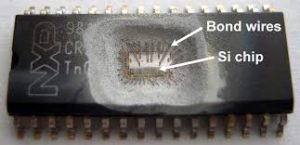
Chip PIC18F2458 Embedded Software Clone
Chip PIC18F2458 Embedded Software Clone include the program and data from both eeprom and flash memory, extract the firmware out from original Microcontroller:
Like previous PIC18 devices, the PIC18F2458 family includes a feature that allows the device clock source to be switched from the main oscillator to an alternate low-frequency clock source.
PIC18F2458 devices offer two alternate clock sources. When an alternate clock source is enabled, the various power managed operating modes are available.
Essentially, there are three clock sources for these devices:
• Primary oscillators
• Secondary oscillators
• Internal oscillator block
The primary oscillators include the External Crystal and Resonator modes, the External RC modes, the External Clock modes and the internal oscillator block.
The particular mode is defined by the FOSC3:FOSC0 configuration bits. The details of these modes are covered earlier in this chapter.
The secondary oscillators are those external sources not connected to the OSC1 or OSC2 pins. These sources may continue to operate even after the controller is placed in a power managed mode. PIC18F2458 devices offer the Timer1 oscillator as a secondary oscillator.
This oscillator, in all power managed modes, is often the time base for functions such as a real-time clock. Most often, a 32.768 kHz watch crystal is connected between the RC0/T1OSO/T13CKI and RC1/T1OSI pins. Like the LP mode oscillator circuit, loading capacitors are also connected from each pin to ground.
The Timer1 oscillator is discussed in greater detail in Section 12.3 “Timer1 Oscillator”. In addition to being a primary clock source, the internal oscillator block is available as a power managed mode clock source. The INTRC source is also used as the clock source for several special features, such as the WDT and Fail-Safe Clock Monitor. The clock sources for the PIC18F2458 devices are shown in Figure 2-8. See Section 23.0 “Special Features of the CPU” for Configuration register details.
The OSCCON register (Register 2-2) controls several aspects of the device clock’s operation, both in full power operation and in power managed modes. The System Clock Select bits, SCS1:SCS0, select the clock source. The available clock sources are the primary clock (defined by the FOSC3:FOSC0 configuration bits), the secondary clock (Timer1 oscillator) and the internal oscillator block. The clock source changes immediately after one or more of the bits is written to, following a brief clock transition interval. The SCS bits are cleared on all forms of Reset when eeprom.