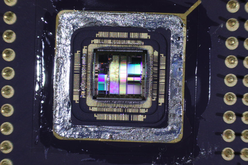
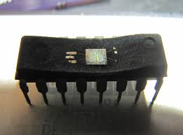
Break MCU IC Texas Instruments MSP430G2452IPW14R
The Texas Instruments MSP430G2452 is a widely used microcontroller (MCU) designed for low-power applications, including industrial automation, consumer electronics, and embedded systems. This chip features built-in secured memory, ensuring that critical firmware, source code, and binary files remain protected against unauthorized access. However, in certain situations, recovering or analyzing the program stored within the MCU becomes necessary, leading to efforts to break its security measures.
Understanding MCU Security and Protection
The MSP430G2452 incorporates multiple protection mechanisms to prevent unauthorized data retrieval. These include flash encryption, locked debugging interfaces, and EEPROM security features. These security measures are designed to safeguard firmware, memory archives, and program files from external threats, ensuring device integrity and preventing unauthorized duplication.
When an MCU becomes locked due to forgotten access credentials, system failures, or loss of backup firmware, there may be a legitimate need to extract, decrypt, or replicate its stored data. Companies and engineers may attempt to recover or restore the original source code for maintenance, debugging, or system upgrades. However, bypassing these security mechanisms presents significant technical challenges.

Challenges in Breaking the MSP430G2452
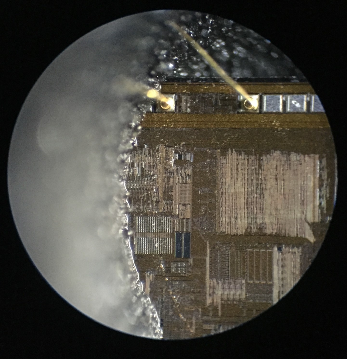
Attempting to break the protection of the MSP430G2452 requires a deep understanding of reverse engineering techniques and embedded system architectures. Some key challenges include:
Advanced Encryption – The MCU employs encryption to prevent direct access to the firmware, making it difficult to decrypt and extract meaningful data.
Debug Interface Lockout – The JTAG or SPI interface is often disabled or protected, restricting standard debugging tools from accessing the internal memory and EEPROM.
Tamper-Resistant Memory – The flash storage is designed to erase itself or become permanently inaccessible if an unauthorized access attempt is detected.
Data Reconstruction Complexity – Even if partial binary files are recovered, reconstructing the full source code is a challenging task requiring sophisticated analysis and reverse engineering skills.
Legal and Ethical Considerations
Efforts to break a secured MCU must be approached with caution, ensuring compliance with ethical and legal guidelines. Unauthorized hacking, cracking, or extracting of proprietary firmware may violate intellectual property laws. Therefore, professionals should always seek proper authorization before engaging in MCU security analysis or data recovery.
Break MCU IC Texas Instruments MSP430G2452IPW14R starts from acquiring its basic structure:
Low Supply Voltage Range: 1.8 V to 3.6 V
Ultra-Low Power Consumption
– Active Mode: 220 µA at 1 MHz, 2.2 V
– Standby Mode: 0.5 µA
– Off Mode (RAM Retention): 0.1 µA
Ultra-Fast Wake-Up From Standby Mode in Less Than 1 µs
16-Bit RISC Architecture, 62.5-ns Instruction Cycle Time
Basic Clock Module Configurations
– Internal Frequencies up to 16 MHz With Four Calibrated Frequencies
– Internal Very-Low-Power Low-Frequency (LF) Oscillator
– 32-kHz Crystal
– External Digital Clock Source One 16-Bit Timer_A With Three Capture/Compare Registers
Up to 16 Touch-Sense Enabled I/O Pins
Universal Serial Interface (USI) Supporting SPI and I2C
10-Bit 200-ksps Analog-to-Digital (A/D)
Converter With Internal Reference, Sample-and-Hold, and Autoscan (MSP430G2x52 Only)
On-Chip Comparator for Analog
Brownout Detector Serial Onboard Programming,
No External Programming Voltage Needed,
Programmable Code Protection by Security Fuse
On-Chip Emulation Logic With Spy-Bi-Wire Interface
Family Members are Summarized in Table 1 Package Options
– TSSOP: 14 Pin, 20 Pin
– PDIP: 20 Pin
– QFN: 16 Pin
For Complete Module Descriptions, See the MSP430x2xx Family User’s Guide (SLAU144)