-
Product Categories
Live Support Chat


Attack MCU PIC16F636 Binary
Attack MCU PIC16F636 tamper resistance system, disable the security fuse inside microcontroller PIC16F636, recover microprocessor binary out from its flash memory;
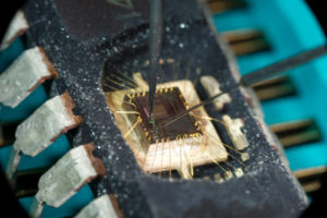
Attack MCU PIC16F636 tamper resistance system, disable the security fuse inside microcontroller PIC16F636, recover microprocessor binary out from its flash memory;
Timer1 Operation in Asynchronous Counter Mode
If control bit T1SYNC (T1CON<2>) is set, the external clock input is not synchronized. The timer continues to increment asynchronous to the internal phase clocks. The timer will continue to run during SLEEP and can generate an interrupt on overflow, which will wake-up the processor. However, special precautions in software are needed to read/write the timer after Microchip PIC16F628A MCU binary recovery.
Timer1 Oscillator
A crystal oscillator circuit is built-in between pins OSC1 (input) and OSC2 (amplifier output). It is enabled by setting control bit T1OSCEN (T1CON<3>). The oscillator is a low power oscillator rated up to 32 kHz. It will continue to run during SLEEP. It is primarily intended for a 32 kHz crystal. Table 9-2 shows the capacitor selection for the Timer1 oscillator. The Timer1 oscillator is shared with the system LP oscillator. Thus, Timer1 can use this mode only when the system clock is derived from the internal oscillator.
Asynchronous Counter Mode.
As with the system LP oscillator, the user must provide a software time delay to ensure proper oscillator start-up.
TRISA5 and TRISA4 bits are set when the Timer1 oscillator is enabled. RA5 and RA4 read as ‘0’ and TRISA5 and TRISA4 bits read as ‘1’
The Timer1 oscillator is shared with the system LP oscillator. Thus, Timer1 can use this mode only when the system clock is derived from the internal oscillator when Microchip MCU PIC16F818 content reading .
Asynchronous Counter Mode.
Reading TMR1H or TMR1L, while the timer is running from an external asynchronous clock, will ensure a valid read (taken care of in hardware). However, the user should keep in mind that reading the 16-bit timer oscillator is enabled. RA5 and RA4 read as ‘0’ and TRISA5 and TRISA4 bits read as ‘1’ in two 8-bit values itself, poses certain problems, since the timer may overflow between the reads.
For writes, it is recommended that the user simply stop the timer and write the desired values. A write contention may occur by writing to the timer registers, while the register is incrementing. This may produce an unpredictable value in the timer register.
Reading the 16-bit value requires some care. Examples 12-2 and 12-3 in the PICmicro™ Mid-Range MCU Family Reference Manual (DS33023) show how to read and write Timer1 when it is running in Asynchronous mode.